Description
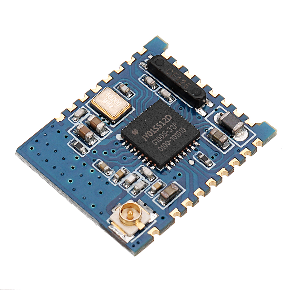
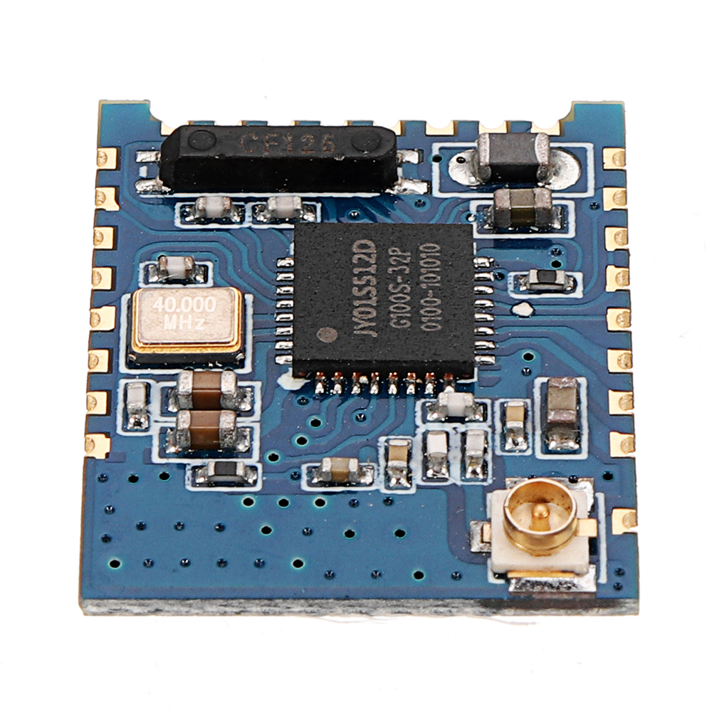
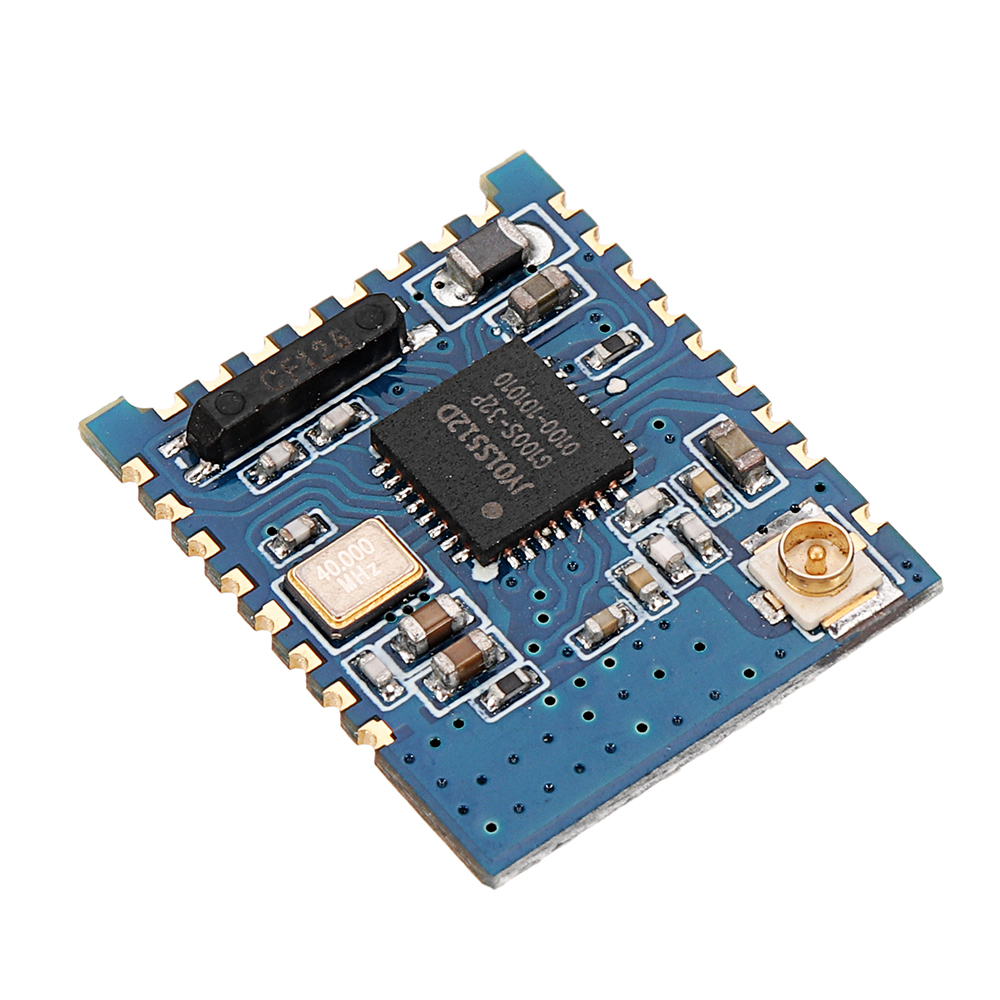
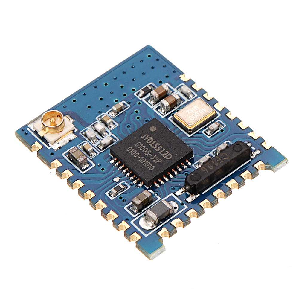
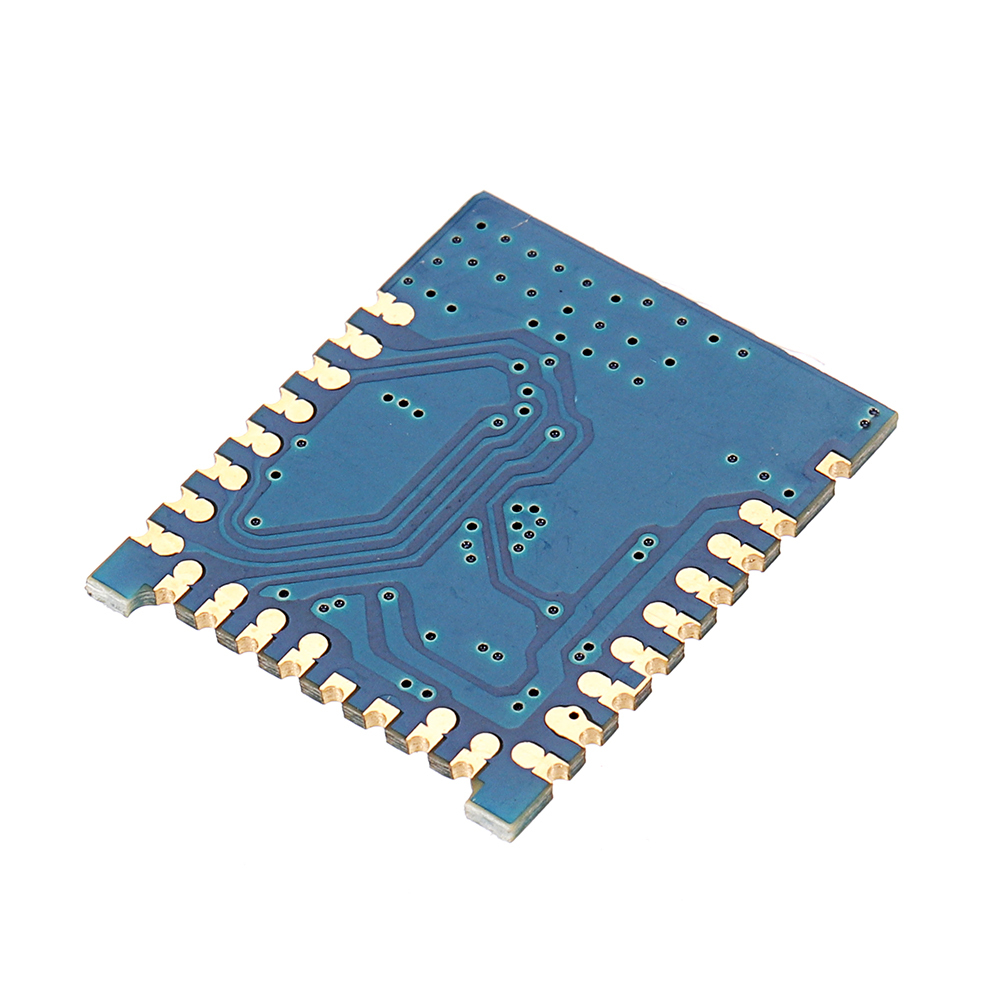
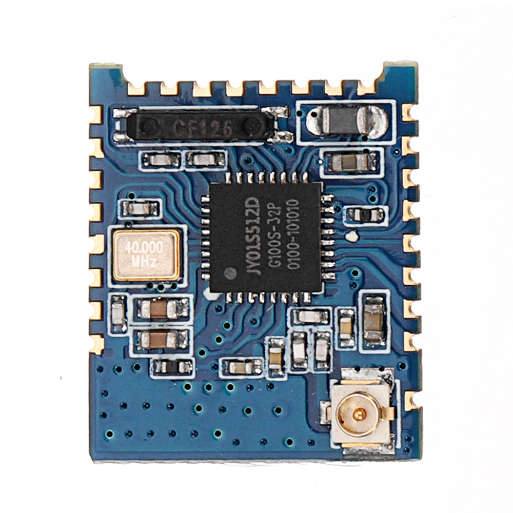
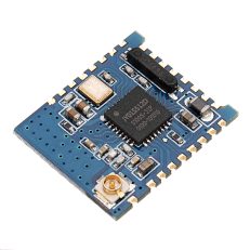
Product introduction:The JDY-17 transmission module is based on the bluetooth 4.2 protocol standard, the working band is 2. 4GHZ range, the modulation mode is GFSK, the maximum transmission power is Odb, the maximum launch distance is 60 meters. The import original chip is designed to support the user to modify the equipment name, service UUID, transmit power, match the password and so on through the AT command. Czechoslovakia is flexible.JDY-17 bluetooth module can realize data transmission of module and cell phone or module and module, and can choose UART or IIC communication mode through I0, and BLE bluetooth can be used for product application quickly through simple configuration.Module parameter details:
| JDY-17 product parameters | |
| Model | JDY-17 |
| Work band | 2.4G |
| Emission power | Odb (maximum) |
| Communication interface | UART or IIC |
| Working voltage | 1.8V-3.3V |
| Working temperature | -40℃ -80℃ |
| Storage temperature | -40℃ -80℃ |
| Antenna | external antenna |
| Receiving sensitivity | -97dbm |
| Transmission distance of | 60 meters |
| Module size | 18mm* 14.94 *2.6 |
| bluetooth version | BLE4.2 (compatible BLE4.0 BLE 4.1) |
| Transmission rate | 115200bps/s |
| Wake-up state current | 4.9mA (broadcast) |
| Shallow sleep state current | <300uA (broadcast) |
| Deep sleep current | 1.8uA (no broadcast) |
| Instruction parameter preservation | Parameter configuration of power down data is saved |
| STM welding temperature | <300℃ |
Working current:
| Working mode | Broadcast state | Current | Remark |
| Awaken | Broadcast | 4. 9mA | Generally speaking with APP, it is suggested that broadcasting should not be too long and too long to affect connection time. It is generally recommended between 100 and 500mS, such as fast connection and no demand for power consumption. The broadcast interv al can be set to the shortest possible. |
| Deep sleep free sleep | NO broadcast | 1.38uA | |
| Shallow sleep has radio sleep | 100mS Broadcast interval | 280uA | |
| Average power consumption | 200mS Broadcast interval | 140uA | |
| 300mS Broadcast interval | 80uA | ||
| 400mS Broadcast interval | The following current is lower | ||
| 500mS Broadcast interval | |||
| 600mS Broadcast interval | |||
| 700mS Broadcast interval | |||
| 800mS Broadcast interval | |||
| 900mS Broadcast interval | |||
| 1000mS Broadcast interval | |||
| internal state of arousal | Already connected | 4. 93mA | In connection state, you can check the AT +STARTEN instruc tion by pulling the PWRC pin down and Issuing the AT instruction or the direct pivoting mode. |
| Sleep state | Already connected | 50uA |
Pin function description:
| Pin | Function | Explain |
| 1 | VCC | Power supply <1.8-3 |
| 2 | PWM1 | Support UART, IIC, APP control |
| 3 | PWM2 | Support UART, IIC, APP control |
| 4 | 104 | High and low levels can be controlled by APP |
| 5 | NULL | |
| 6 | STAT | UART communication mode: unconnected low level, high level aft er connection.IIC communication mode: no connection to high level, connection, disconnection or reception will be interrupted by “interrupt” work, interrupt down edge hold time 200ms |
| 7 | NULL | |
| 8 | NULL | |
| 9 | 101 | High and low levels can be controlled by APP |
| 10 | 102 | High and low levels can be controlled by APP |
| 11 | NULL | |
| 12 | MILL | |
| 13 | 103 | High and low levels can be controlled by APP |
| 14 | PWH3 | Support UART, IIC, APP control |
| 15 | TO4 | Support UART, IIC, APP control |
| 16 | MILL | |
| 17 | ALKD | Broadcast scintillation, frequent connection after connection (master and slave effectiveness) |
| 18 | RTCA | RTC timing time produces the falling edge interrupt signal, normally high level. |
| 19 | TXD_0R_DD | SELECT boot for high power, this pin function is serial TXD.SELECT boot for low power, this pin function is IIC DD |
| 20 | RXD_0R_DC | SELECT boot for high power, this pin function is serial RXD.SELECT boot for low power, this pin function is IIC DC |
| 21 | SELECT | UART or IIC selection pinOpen low level: IIC communication modeOpen high level: UART communication modeThe default SELECT is suspended to high level: UART communication mode. When the user needs IIC, the SELECT pin should be grounded. |
| 22 | PWRC | Down wake-up, when the AT command needs to be sent in the connection state, the AT instruction mode can be expressed by keeing this pin low level, and the pin is AT instruction mode at high and low levels in the unconnected state. |
| 23 | RESET | Hardware reset pin |
| 24 | GND | Power supply |
Serial AT instruction set: JDY-17 module serial port to send AT instructions must add rn, AT is not case sensitive.
| Sequence | Instructions | Effect | Master / slave | Working mode | Default |
| 1 | AT+PERM | APP permission configuration | S | I0,PWM Make energy | |
| 2 | AT+RST | reset | M/S | ||
| 3 | AT+H0STEN | Master and subordinate setting | M/S | Slave machine | |
| 4 | AT+MAC | Device MAC | M/S | ||
| 5 | AT+BAUD | Baud rate | M/S | 9600 | |
| 6 | AT+NAME | Broadcast name | S | JDY-17 | |
| 7 | AT+C0NN | Host connection slave | M | ||
| 8 | AT+SCAN | Host scanning slave | M | ||
| 9 | AT+BAND | Host bindings from the machine MAC | M | 000000000000 | |
| 10 | AT+USTP | Serial stop bit | M/S | 0 | |
| 11 | AT+SLEEP | Sleep | M/S | ||
| 12 | AT+PARITY | Serial parity check bit | M/S | 0 | |
| 13 | AT+PASS | Slave connection password | S | 123456 | |
| 14 | AT+STARTEN | Working mode of opening | M/S | 0 | |
| 15 | AT+DEFAULT | Restore the factory | M/S | ||
| 16 | AT+FLOWC | Serial flow control | M/S | 0 | |
| 17 | AT+VER | Version number | M/S | JDY-17-V1.0 | |
| 18 | AT+ISCEN | Slave connection cipher switch | M/S | 0 |
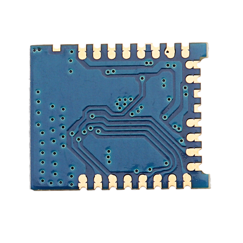
Package included: 1 x JDY-17 bluetooth 4.2 Module High Speed Data Transmission Mode BLE Mesh Networking Low Power.

 or 4 payments of


Reviews
There are no reviews yet.