Description
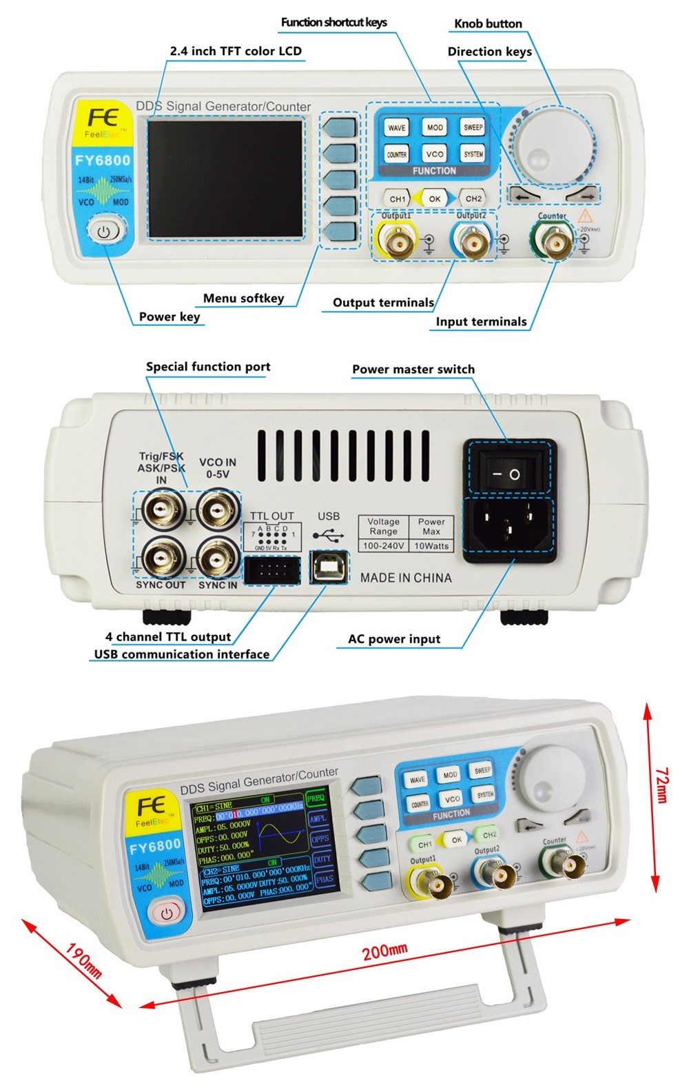
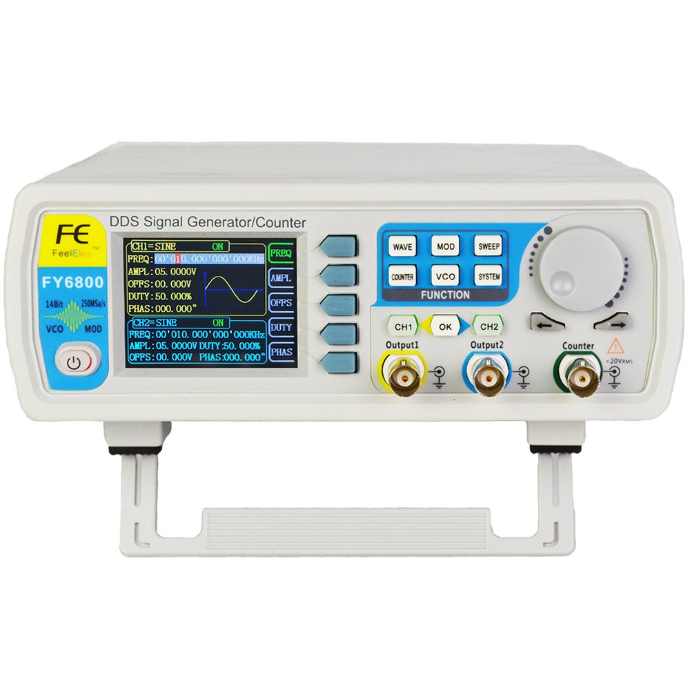
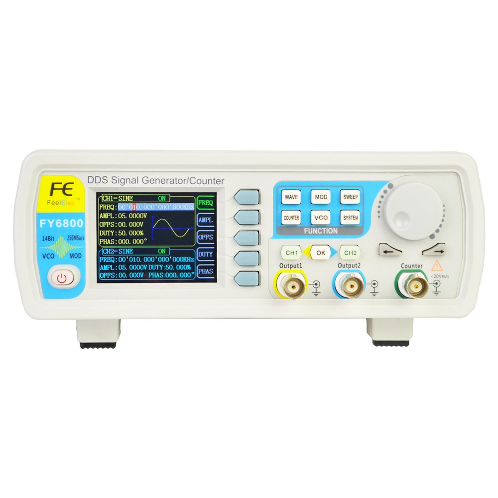
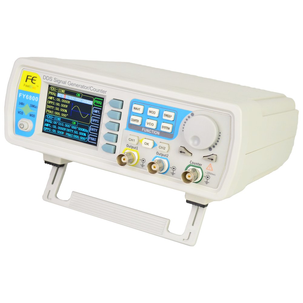
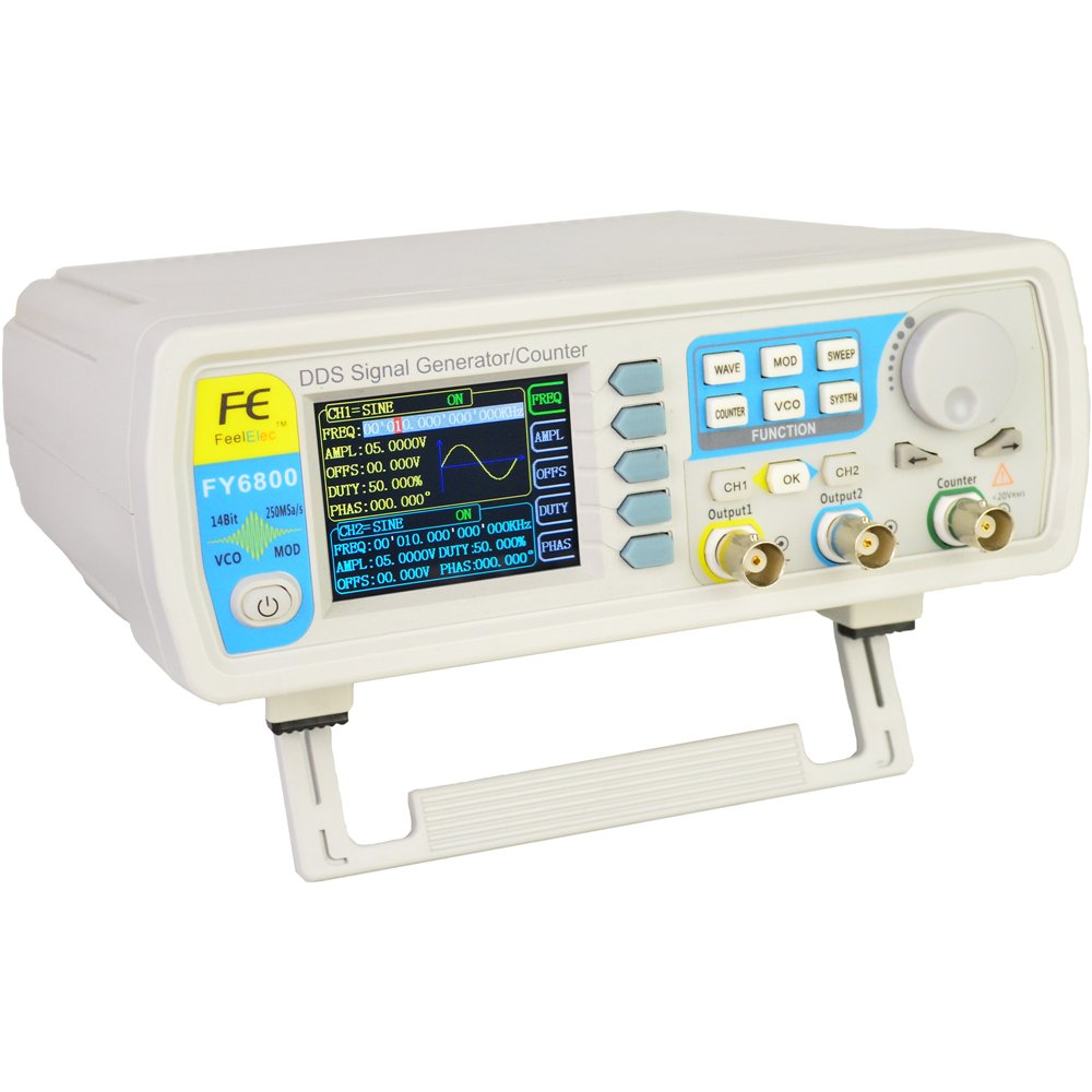
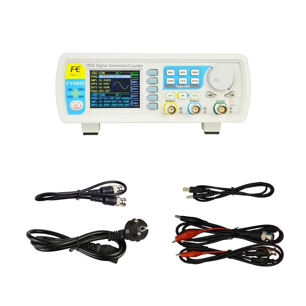
Abundant shortcut keys and graphical user interface simplifies every operation.
Users do not have to spend a lot of time to learn and familiar with the operation of the instrument, you can be skilled use.
For education, research and development, production, testing, maintenance and other industries to provide a new choice.
The instrument adopt the Direct Digital Synthesizer (DDS) technology and provide stable, precise, pure and low distortion signals.
Surface mounting technology improves interference immunity and operational life span.
Due to communications with extensive users and fully understanding to users’ practice, we regard users’ demand as the most important factor in R&D.
Continuously innovatio’n and listening users’ suggestions, we try to offer customers better products with higher cost performance.
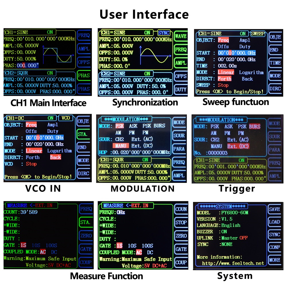
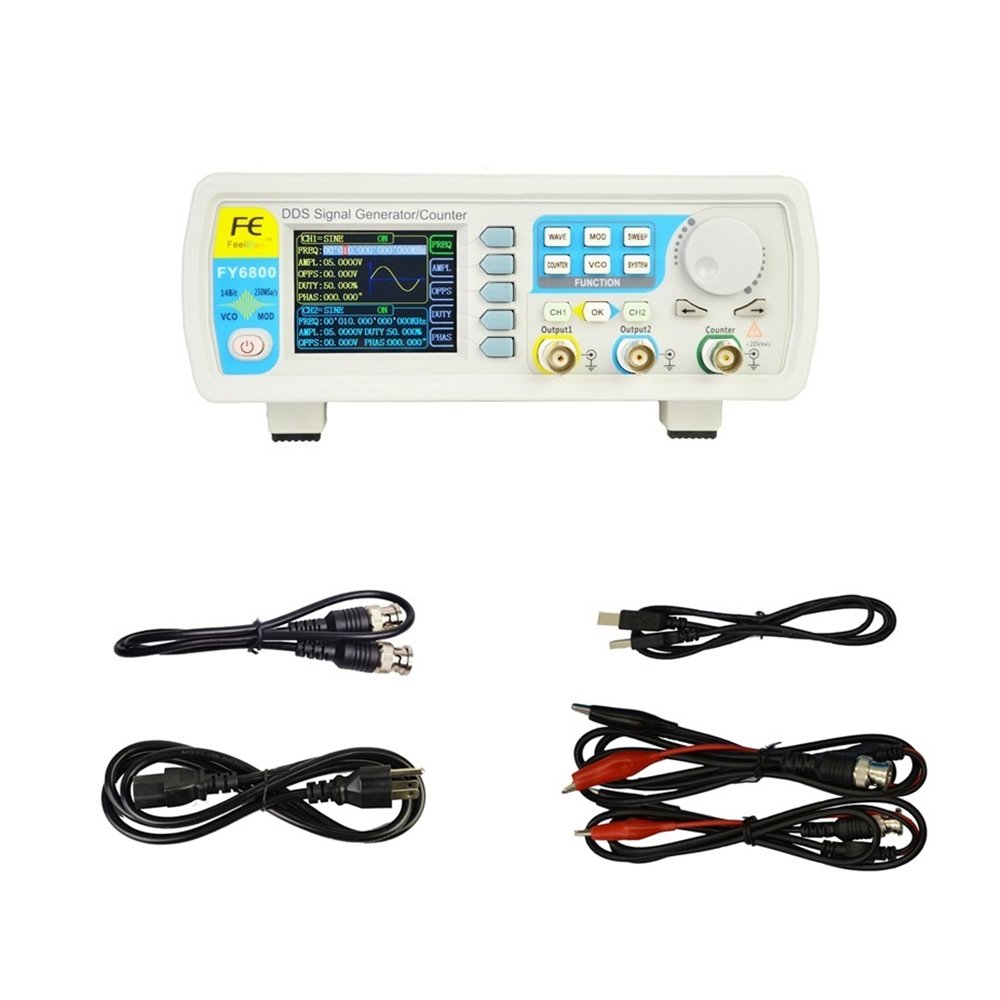
1. FY6800 user interface displays the parameters and waveforms of the two channels at the same time. Each function has a separate user interface, different contents will be displayed when different functions are enabled.
2. The instrument uses 14-bit high-speed D/A converter chip (5Vpp output quantization error is less than 1mV), 250MSa/s sample rate, 14bits vertical resolution.
3. Enable to store 64 arbitrary waveform data files, each one of waveform storage depth 8192 points * 14bits;
4. Various modulation types: AM, FM, PM, ASK, FSK and PSK modulations.
5. VCO Function (Voltage Control Output).
6. The minimu’m output amplitude is 1mV , minimu’m amplitude resolution can be up to 1mV.
7.Precisely adjust the phases of the two channels, Precision can be 0.01°.
8. Duty cycle of each channel can be adjusted separately. Precision can be 0.01%.
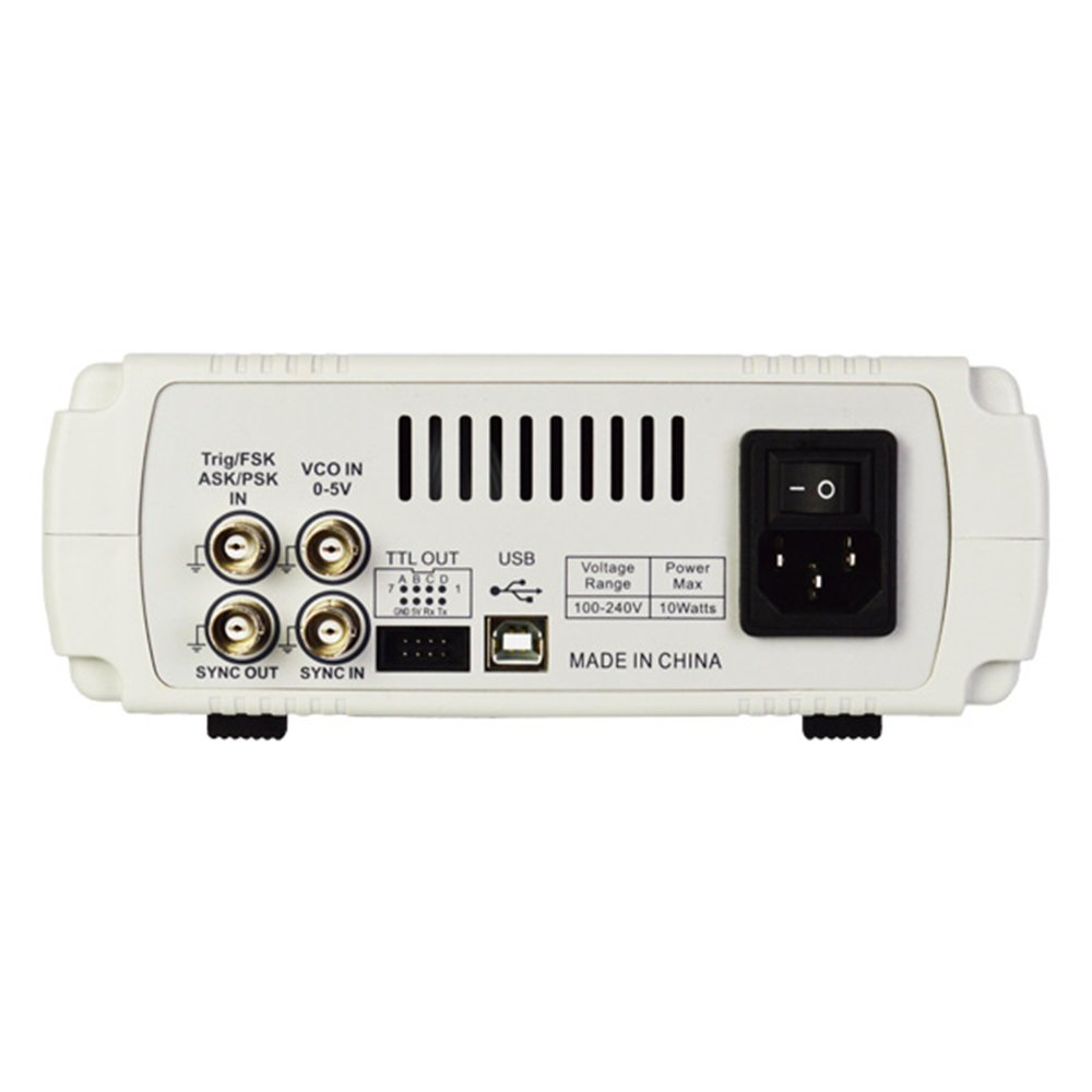
9. 4 Channel TTL Output.
10. Easy to use, powerful PC Software.
Specification :
Unless specified, all specifications can be guaranteed if the following two conditions are met.
The generator has passed self-inspection.
The generator has been working continuously for at least 30 minutes under the specified temperature (18℃~28℃).
All the specifications are guaranteed unless those marked with “typical” .
| Frequency | |||||||||
| Model | FY6800-30M | FY6800-60M | |||||||
| Sine | 0~30MHz | 0~60MHz | |||||||
| Square | 0~20MHz | 0~25MHz | |||||||
| Ramp, Triangle | 0~10MHz | 0~10MHz | |||||||
| Pulse | 0~10MHz | 0~10MHz | |||||||
| TTL/CMOS | 0~20MHz | 0~20MHz | |||||||
| Arbitrary Waveform | 0~10MHz | 0~10MHz | |||||||
| Minimu’m pulse width | 20ns(All models of pulse wave minimu’m width can reach 20ns) | ||||||||
| Min. Resolution on all frequency range | 1μHz (Min. resolution can reach 1μHz on all frequency range to ensure adjusting accuracy under high frequency. For example, it can output 10.000000000001MHz signal). | ||||||||
| Accuracy | ±20ppm | ||||||||
| Stability | ±1ppm/ 3hours | ||||||||
| Waveform Characteristics | |||||||||
| Waveforms | Sine, Square (Duty Cycle adjustable), Pulse (Pulse width and cycle time can be set accurately), Triangle/Ramp, Sawtooth Wave, CMOS, Four channels TTL, DC, Half wave, Full wave, Positive Step, Inverse Step, Positive Exponent, Inverse Exponent, Lorenz Pulse, Multitone, Noise, ECG, Trapezoidal Pulse, Sinc Pulse, Narrow Pulse, Gauss White Noise, AM, FM, and other 64 sets customer-defined waveform. | ||||||||
| Non-Volatile Storage | Can store 64 user-defined arbitrary waveforms, (8K 14bits) * 64 | ||||||||
| Waveform Length | 8192 points * 14bits | ||||||||
| Sampling Rate | 250MSa/s | ||||||||
| Vertical Resolution | 14 bits | ||||||||
| Sine | Harmonic Suppression | ≥50dBc(<1MHz); ≥45dBc(1MHz~20MHz); | |||||||
| Total Harmonic Distortion | <0.5% (20Hz~20kHz,0dBm) | ||||||||
| Square | Rise/Fall Time | ≤7ns (VPP<5V) | |||||||
| Overshoot | ≤5% | ||||||||
| Duty Cycle | 0.01%~99.99% (Resolution 0.01%) | ||||||||
| Sawtooth wave | Linearity | >99% (0.01Hz~10kHz) | |||||||
| Output characteristics | |||||||||
| Amplitude(VPP) | Frequency≤10MHz: 1mVpp~20Vpp; 10MHz Frequency>20MHz: 1mVpp~5Vpp; |
||||||||
| Resolution | 1mV | ||||||||
| Amplitude Stability | ±0.5%/ 5 Hours | ||||||||
| Amplitude flatness | ±2.5%(<10MHz);±5%(>10MHz); | ||||||||
| Waveform Output | |||||||||
| Impedance | 50Ω±10% (Typical) | ||||||||
| Protection | All channels can work more than 60 seconds when the load is short-circuited. | ||||||||
| DC Offset | |||||||||
| Offset Range | Frequency≤20MHz: ±10V; Frequency>20MHz: ±2.5V; | ||||||||
| Offset Resolution | 1mV | ||||||||
| Phase Feature | |||||||||
| Phase range | 0~359.99° | ||||||||
| Phase resolution | 0.01° | ||||||||
| TTL Output | |||||||||
| TTL Level Amplitude | >3Vpp | ||||||||
| Fan-out | >8 TTL LOAD | ||||||||
| Rise/Fall Time | ≤10ns | ||||||||
| CMOS Output | |||||||||
| Low Electric Level | <0.3V | ||||||||
| High Electric Level | 1V~10V | ||||||||
| Rise/Fall Time | ≤18ns | ||||||||
| External Measurement | |||||||||
| Function | Frequency, Period, Positive/Negative Pulse Width, Duty Cycle | ||||||||
| Input Voltage Range | 1Vpp~20Vpp | ||||||||
| Frequency Meter | Resolution | 0.01Hz (Gate Time = 100S) | |||||||
| Range | 0.01Hz~100MHz | ||||||||
| Sensitivity | Gate Time 3 grades (1S, 10S, 100S) adjustable | ||||||||
| Counter | Range | 0-4294967295 | |||||||
| Coupling | DC, AC | ||||||||
| Working Mode | Manual | ||||||||
| Period | Measurement Range | 5ns ~ 20s | DC coupling measurement | ||||||
| Pulse Width | Measurement Range | 0ns ~ 20s | |||||||
| Resolution | 5ns | ||||||||
| Duty Cycle | Range (Display) | 0% ~ 100% | |||||||
| Sweep | |||||||||
| Carrier Waveform | Sine, Square, Ramp, Arbitrary (except DC) | ||||||||
| Sweep Type | Linear or Logarithm | ||||||||
| Sweep Direction | Up, Down and roundtrip sweep directions; | ||||||||
| Sweep Objects | Frequency, Amplitude, Offset, Duty Cycle | ||||||||
| Sweep Time | 0.01S~999.99S/Step | ||||||||
| Setting range | Starting position and Finishing position can be set arbitrarily. | ||||||||
| Sweep Range | Decided by Parameters setting. | ||||||||
| VCO (Voltage Control Output) | |||||||||
| Modulation signal range to input | 0~5V | ||||||||
| VCO signal frequency range | 0-1000Hz | ||||||||
| VCO control object | voltage controlling frequency (VCF), voltage controlling amplitude (VCA), voltage controlling offset, voltage controlling duty cycle. | ||||||||
| VCO special function | Can Amplitude Modulate (AM) or Frequency Modulate (FM) by external analog signal. | ||||||||
| Modulation | |||||||||
| Modulation Type | AM, FM, PM, ASK, FSK, PSK | ||||||||
| Carrier Waveform | Sine, Square, Triangle, Ramp, Arbitrary waveform (Except DC) | ||||||||
| AM | |||||||||
| Source | Internal (CH2) / External (VCO IN Port) | ||||||||
| Modulating Waveform | Sine, Square, Triangle, Ramp, Arbitrary waveform | ||||||||
| Depth | 0% to 100% | ||||||||
| Modulating Frequency | Internal : 1μHz~1MHz; External: 1μHz~2KHz; | ||||||||
| FM | |||||||||
| Source | Internal (CH2) / External (VCO IN Port) | ||||||||
| Modulating Waveform | Sine, Square, Triangle, Ramp, Arbitrary waveform | ||||||||
| Modulating Frequency | Internal : 1μHz~1MHz; External: 1μHz~2KHz; | ||||||||
| PM | |||||||||
| Source | Internal (CH2) / External (VCO IN Port) | ||||||||
| Modulating Waveform | Sine, Square, Triangle, Ramp, Arbitrary waveform | ||||||||
| Phase Deviation | 0° to 360° | ||||||||
| Modulating Frequency | Internal : 1μHz~1MHz; External: 1μHz~2KHz; | ||||||||
| ASK | |||||||||
| Source | Internal (CH2), External (ASK IN Port), Manual | ||||||||
| Modulating Waveform | Square with 50% duty cycle. | ||||||||
| Key Frequency | 1μHz~10MHz | ||||||||
| FSK | |||||||||
| Source | Internal (CH2), External (FSK IN Port), Manual | ||||||||
| Modulating Waveform | Square with 50% duty cycle. | ||||||||
| Key Frequency | 1μHz~10MHz | ||||||||
| PSK | |||||||||
| Source | Internal (CH2), External (PSK IN Port), Manual | ||||||||
| Modulating Waveform | Square with 50% duty cycle. | ||||||||
| Key Frequency | 1μHz~10MHz | ||||||||
| Burst Function | |||||||||
| Carrier Waveform | Sine, Square, Ramp, Arbitrary (except DC) | ||||||||
| Burst Count | 1~1048575 | ||||||||
| Trigger Source | Manual, Internal, External (AC/DC) | ||||||||
| General Specifications | |||||||||
| Display | Type | 2.4 inch, TFT Color Display. | |||||||
| Save & Load | Amount | 20 | |||||||
| Position | 01 to 20 (01 for start default value) | ||||||||
| Interface | Type | USB to Serial interface | |||||||
| Protocol | Comman’d line mode, providing communication protocols. | ||||||||
| Communicating Speed | 115200bps | ||||||||
| Power | Voltage Range | AC100V~240V | |||||||
| Technic | SMD, LSI, Reliable and durable | ||||||||
| Buzzer | Can be turned on/off by setting. | ||||||||
| Operation | Buttons and knob continuously. | ||||||||
| Environment | Temp.: 0~40℃, Humidity: <80% | ||||||||
| Size | 200mm * 190mm * 90mm (L * W * H) | ||||||||
| Weight | 1000g | ||||||||
| Package Size | 25cm * 21cm * 10cm (L * W * H) | ||||||||
| Package Weight | 1kg(Main engine, accessories and packing materials) | ||||||||
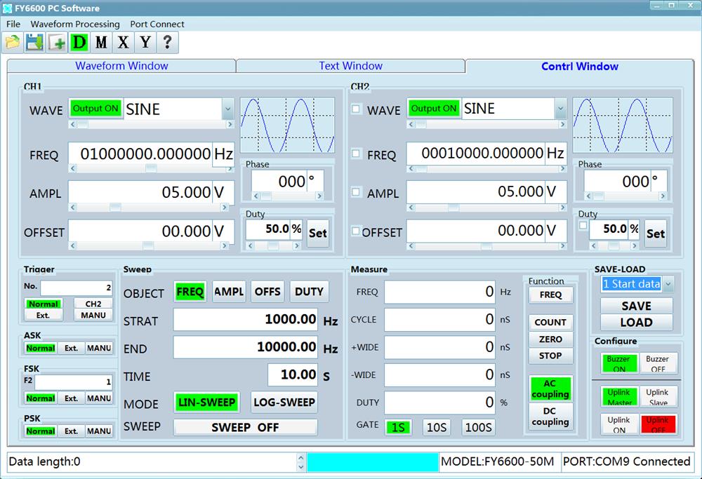
Control window All functional operation intuitive display in the software interface, allowing users to intuitive and rapid adjustment of the instrument function parameters, greatly improve the ease of use of the instrument.
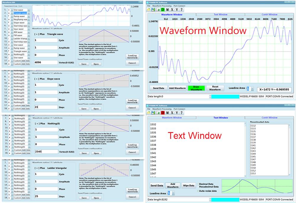
Waveform window and text window has a powerful waveform editing function, can achieve 18 different parameters of any waveform superposition and modulation. Step wave the number of steps can be arbitrarily set between 2 – 4096; Triangle wave vertex positions can be set to realize Ramp waves with different slopes.
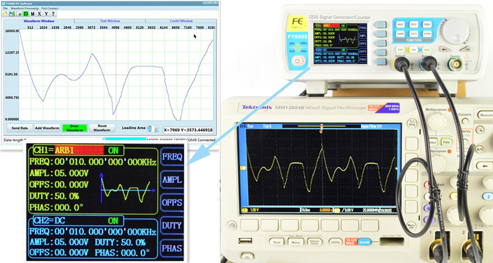
The following figure shows the hand-painted arbitrary waveform, the instrument can support up to 8192 * 14bit arbitrary waveform, can effectively restore more waveform details, especially for medical and automotive maintenance in the field of the required signal simulation.
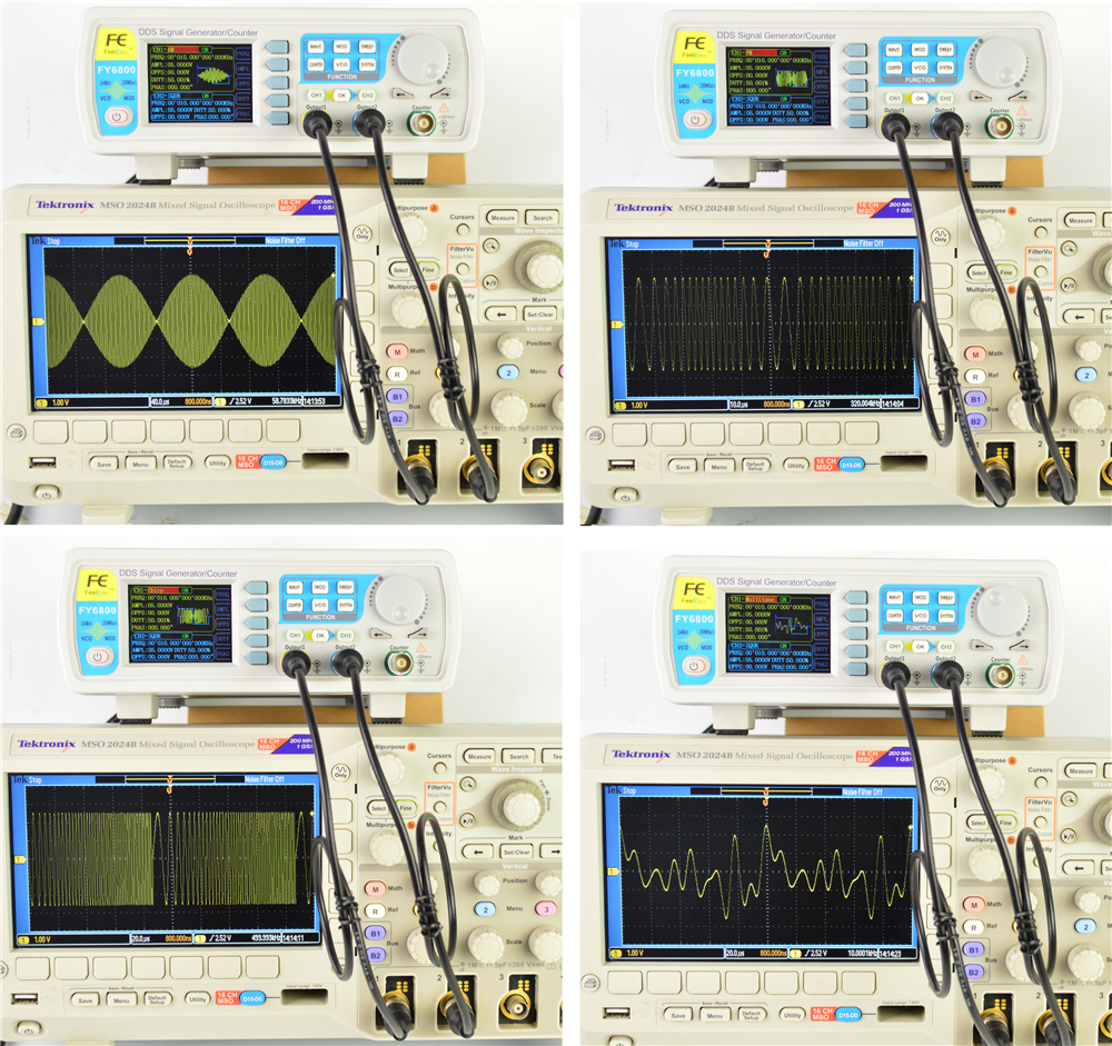
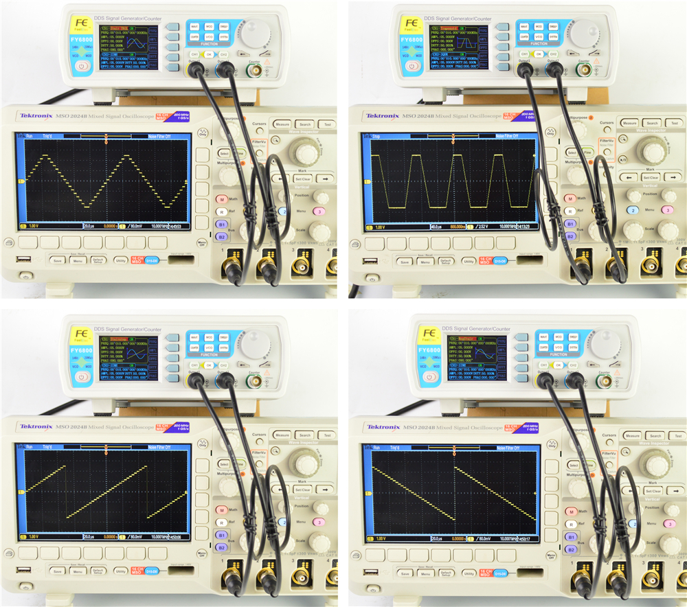
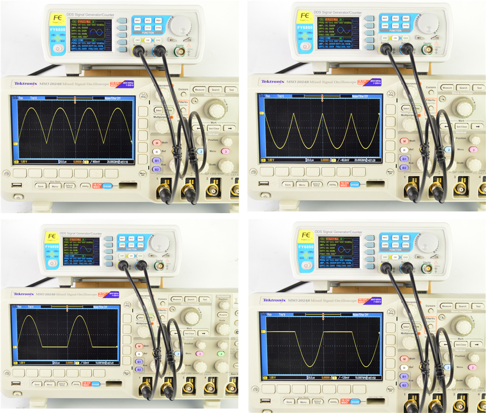
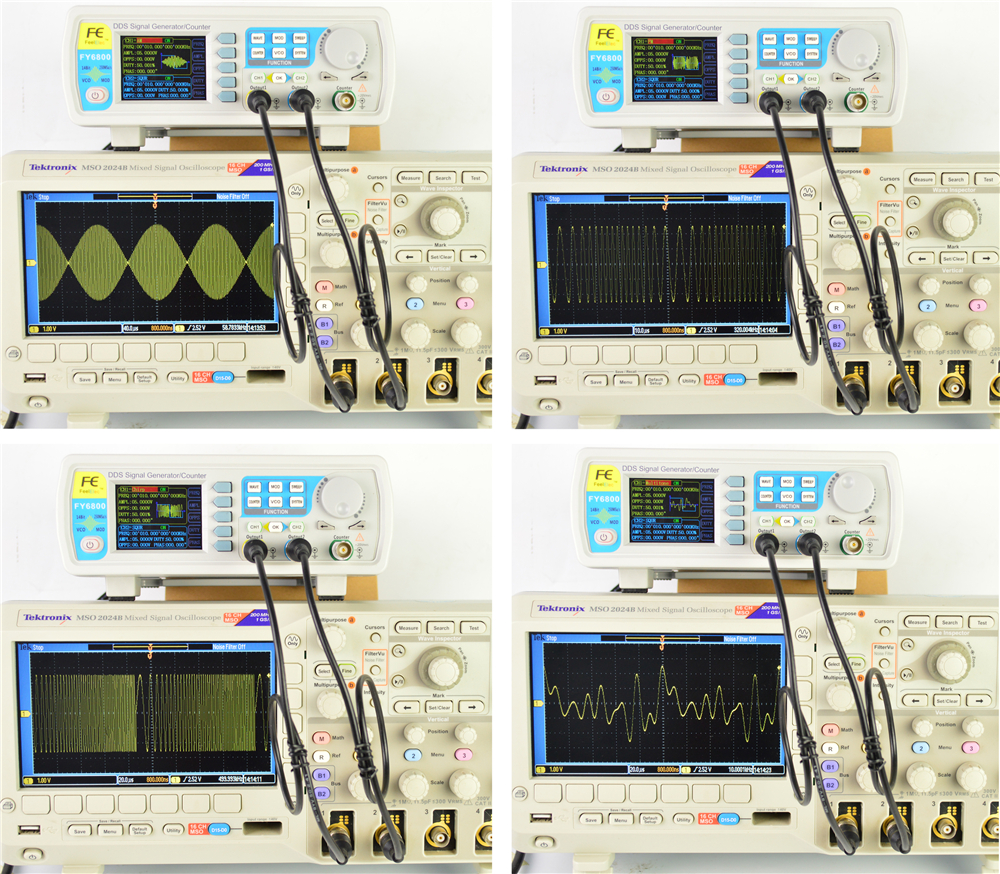
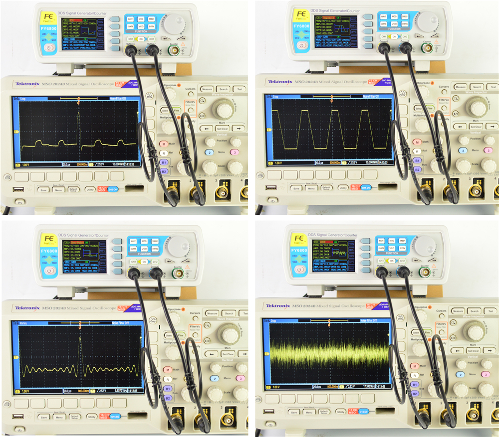
Performance Testing
 ,
,  ,
,  ,
,  ,
,  ,
,  ,
,  ,
,  ,
,  ,
, 



Reviews
There are no reviews yet.