Description
Description:
On board, with relay action switch, relay action or reset can be freely chosen.
The plate is connected with an anti protection diode, and the power supply does not burn the chip or the circuit.
With relay action indicating lamp for convenient observation.
Relay output switch is also charged by pin selection.
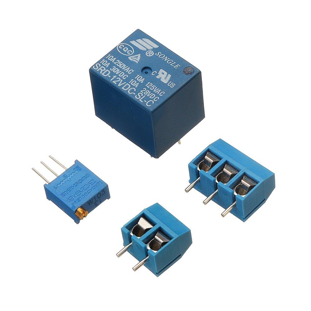
Working Voltage: 12V (Change the working voltage with different relays, if you supply 5V, change to 5V relay)
Input current: greater than 100mA
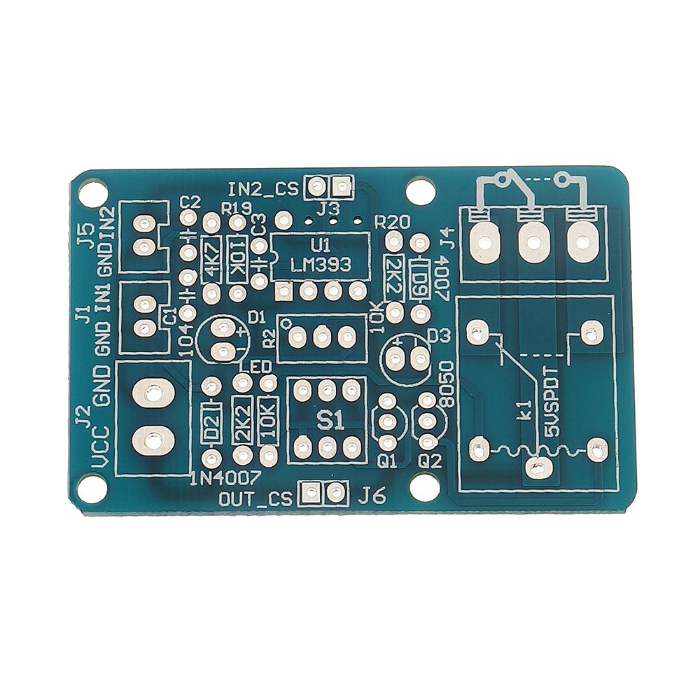
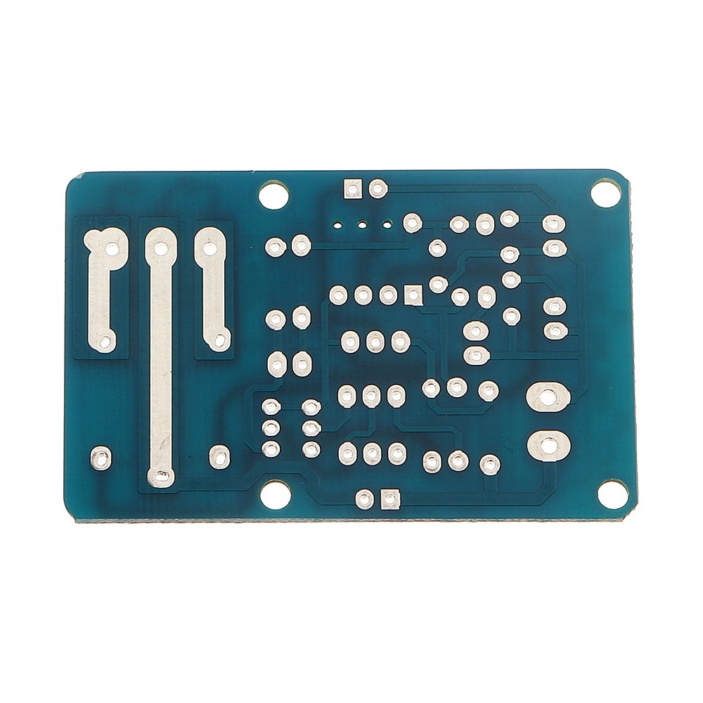
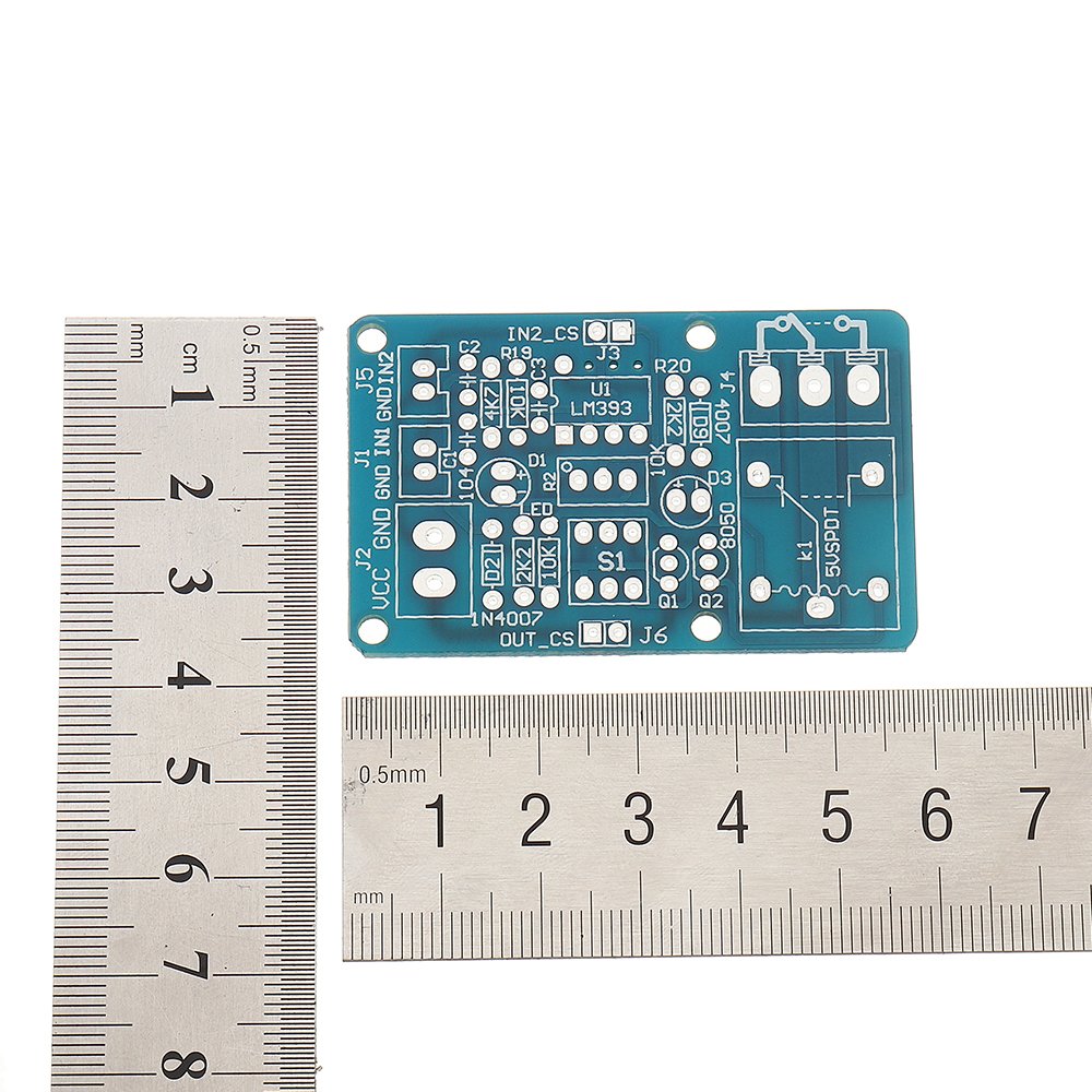
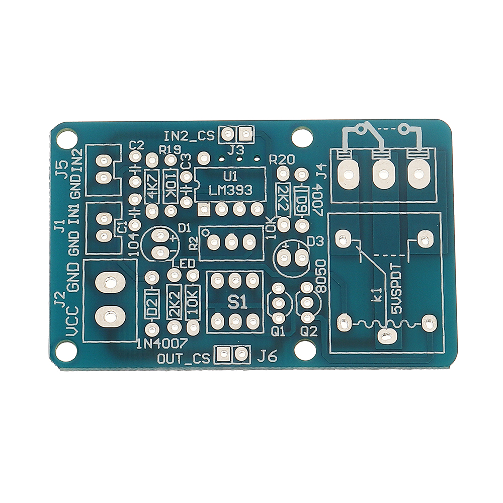
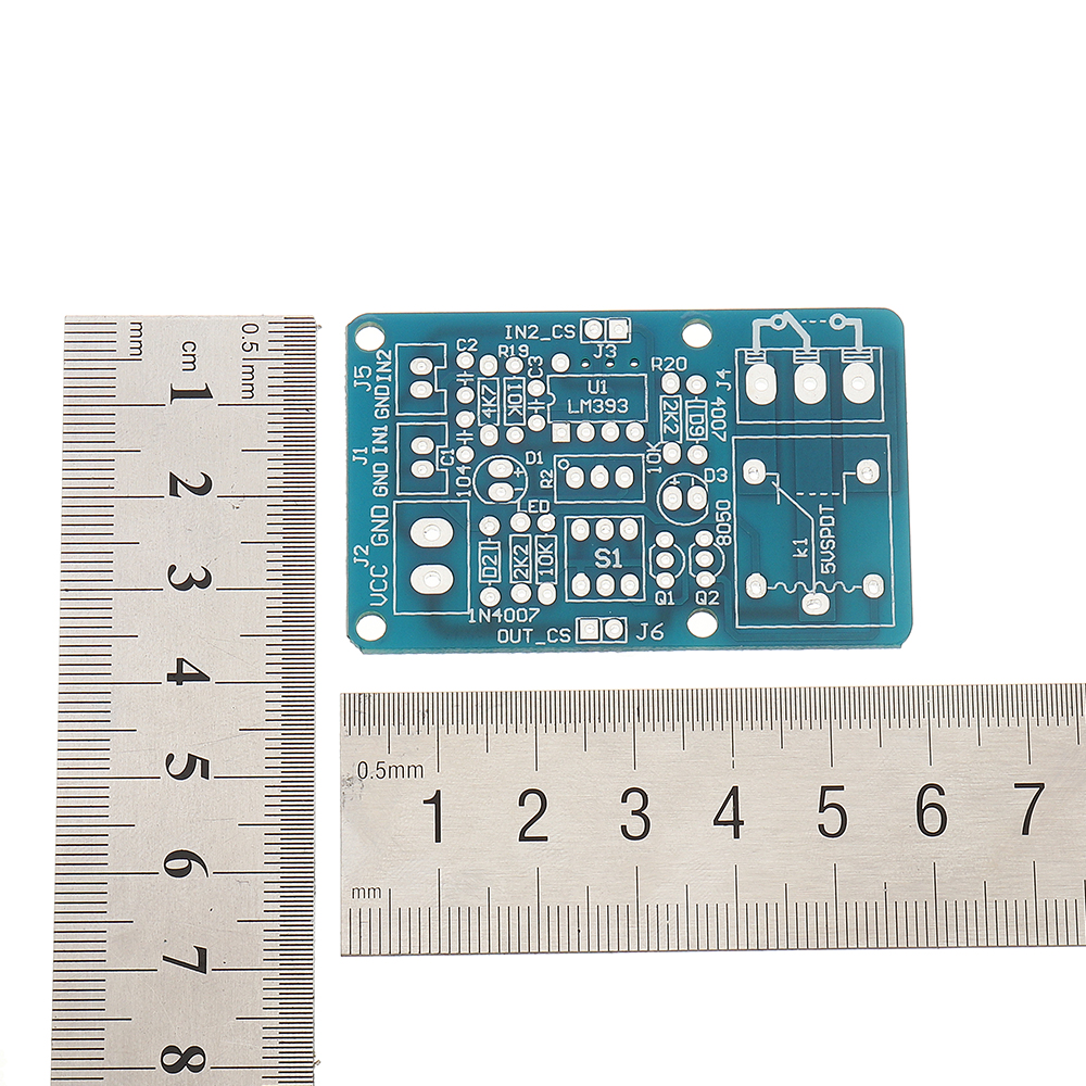
PCB size: 5.8 x 3.7 CM
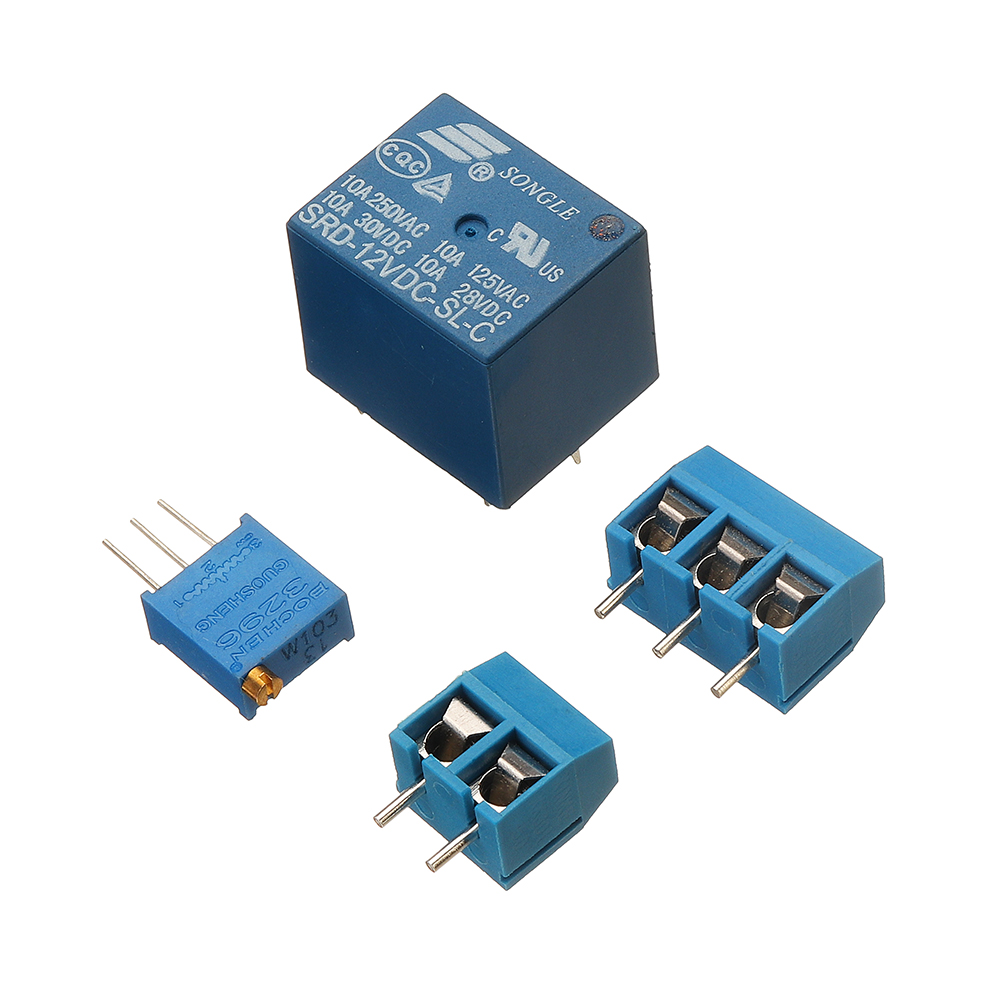
Load: 250V 10A AC or 30V 10A DC (less than the current in this range can be used)
Module function: according to the voltage of the comparator, the relay will act or reset
Function 1: IN2_CS short-circuit cap is plugged in as Selection Function 1, input a voltage (input on J1) compared with the reference voltage set on the module. When the self-locking switch on board is in the spring state, if the input voltage is greater than the reference voltage, the relay operates, otherwise the relay resets; when the self-locking switch on board is in the press state. If the input voltage is greater than the reference voltage, the relay resets (that is, the relay does not operate), and vice versa.
Function 2: The IN2_CS short-circuit cap is taken down as Selection Function 2, and two voltage signals are input for comparison (input in J1 and J5, input in J1 and input in J5, input in IN1 and input in J5). When the self-locking switch on board is in a spring state, if the input voltage IN1 is greater than the IN2 voltage, the relay operates, otherwise the relay resets; when the self-locking switch on board is in a spring state. When the lock switch is pressed, if the input voltage IN1 is greater than the IN2 voltage, the relay resets (that is, the relay does not operate), and vice versa, the relay operates.
Package Included:
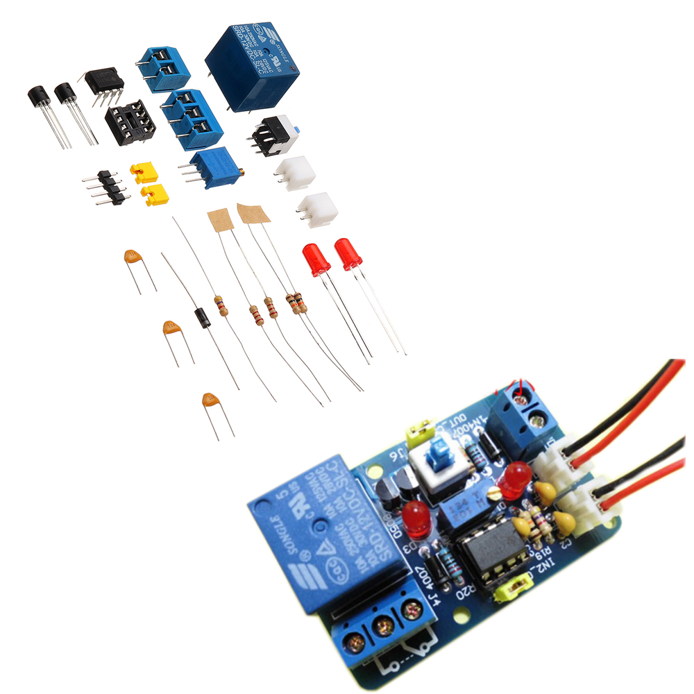
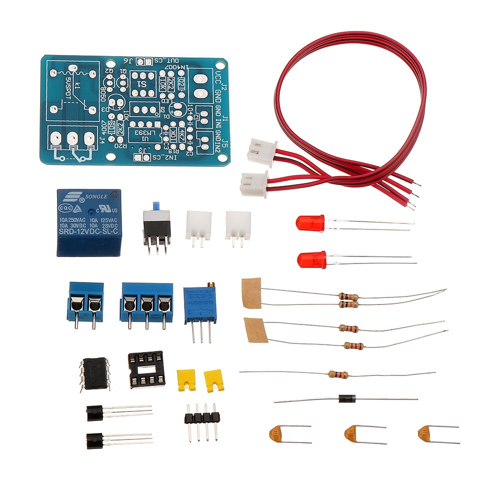
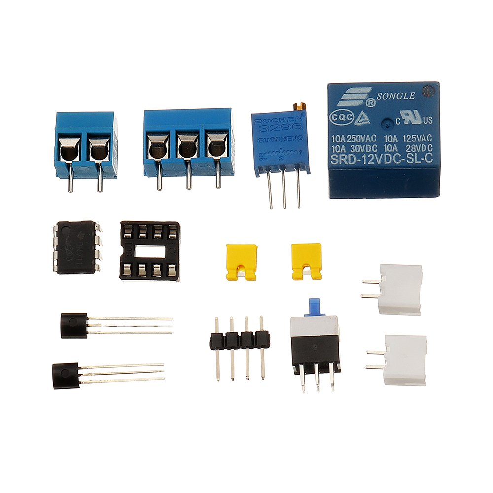
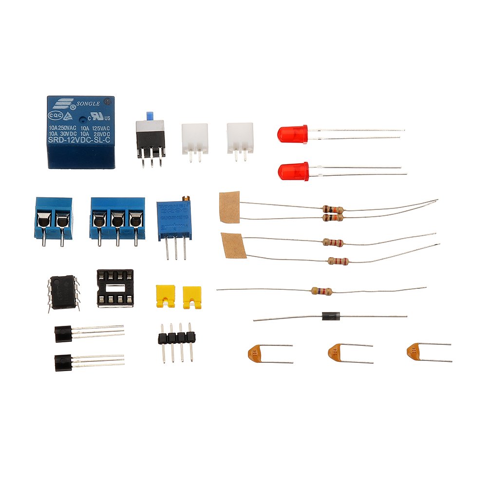
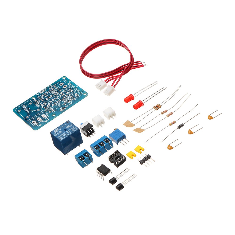
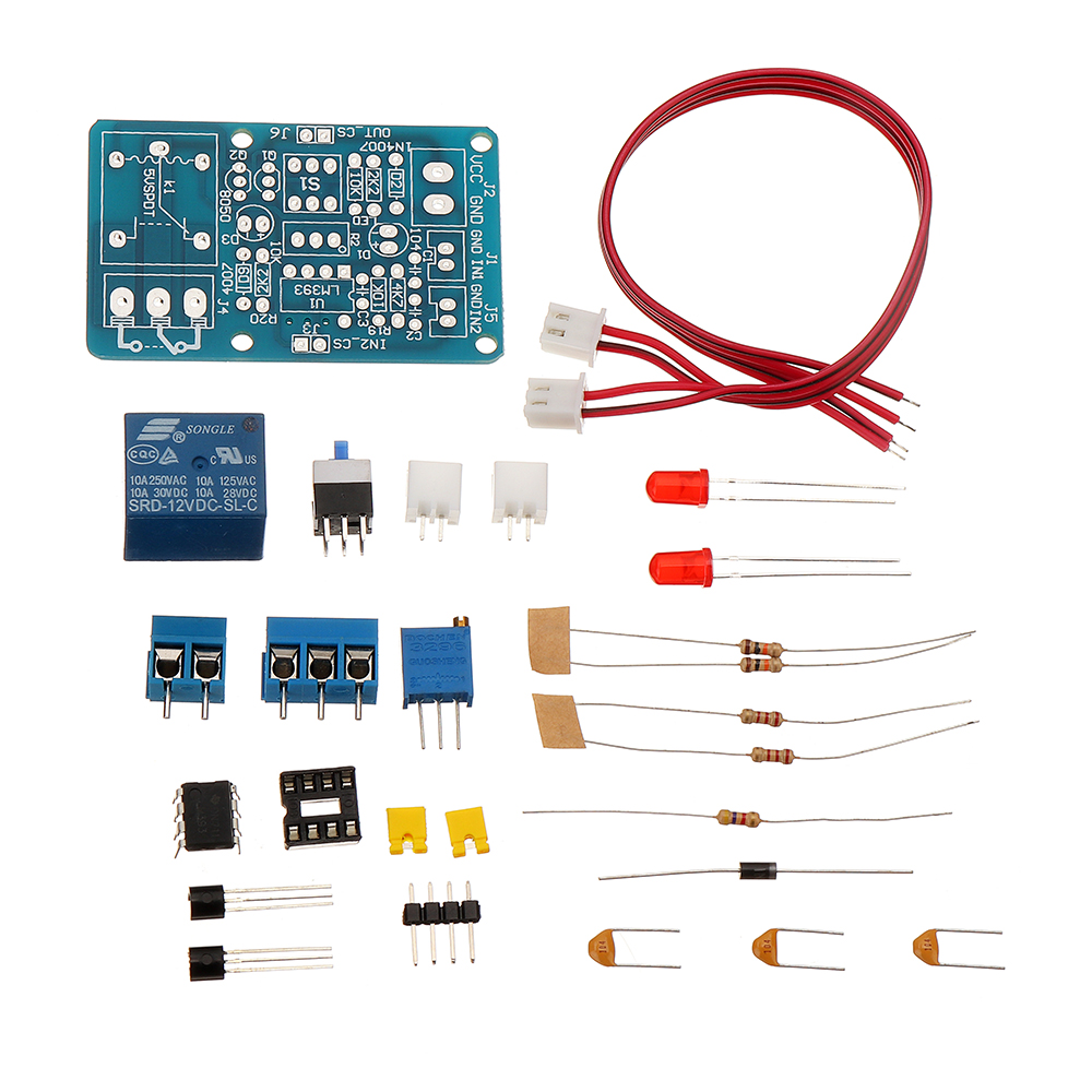
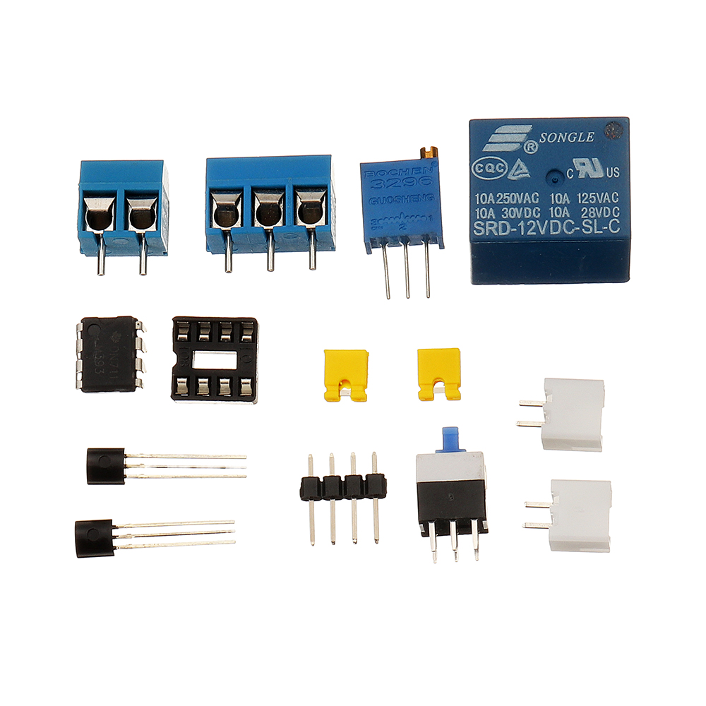
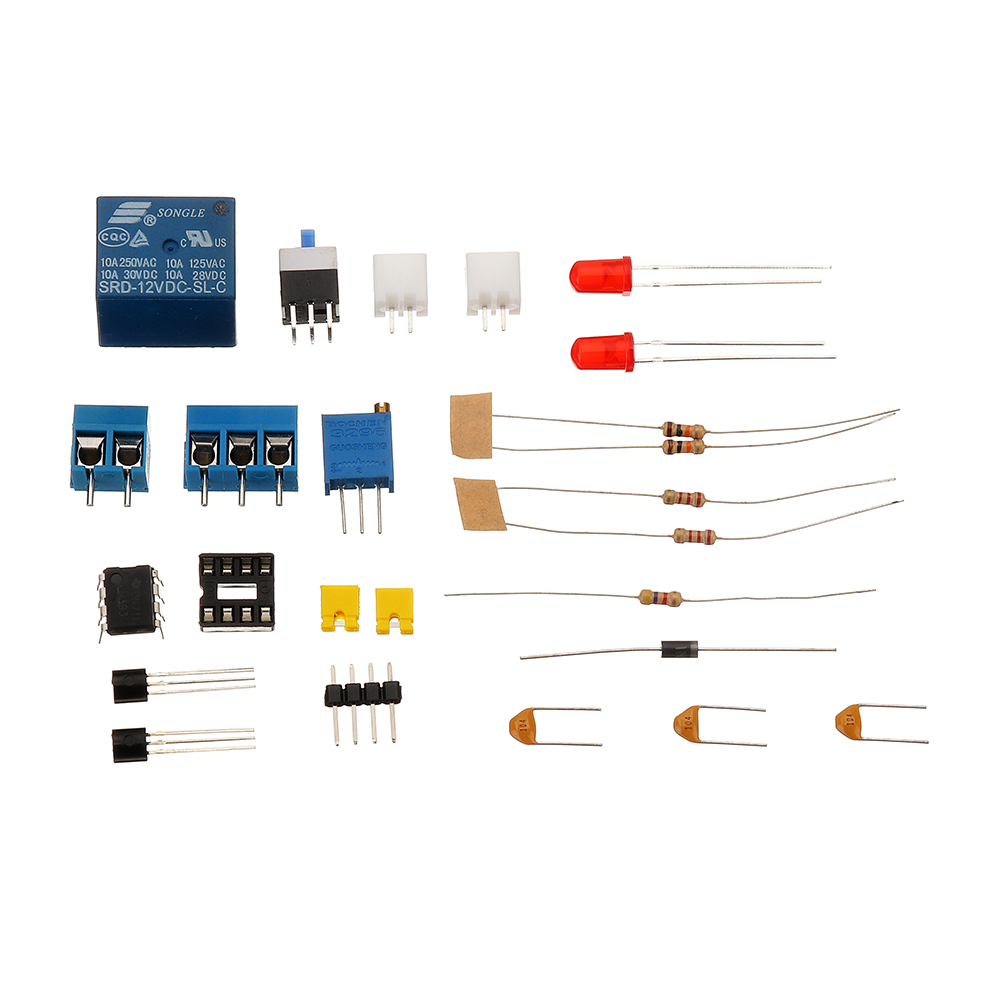
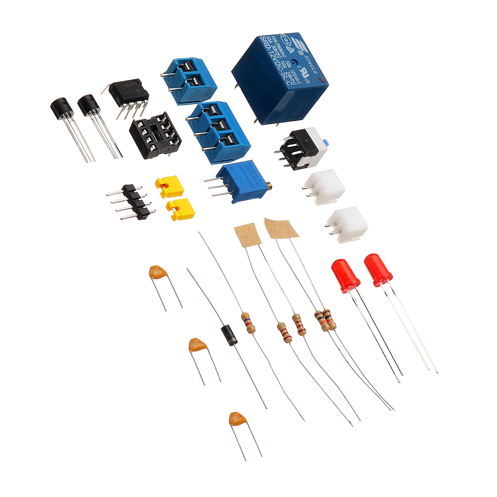
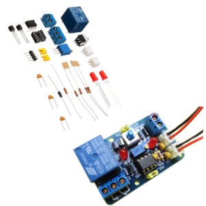
1 x DIY LM393 Voltage Comparator Module Kit







Reviews
There are no reviews yet.