Description
Description:
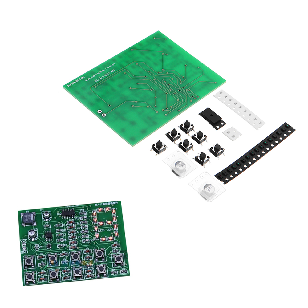
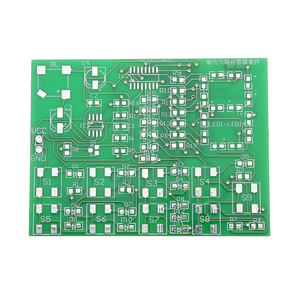
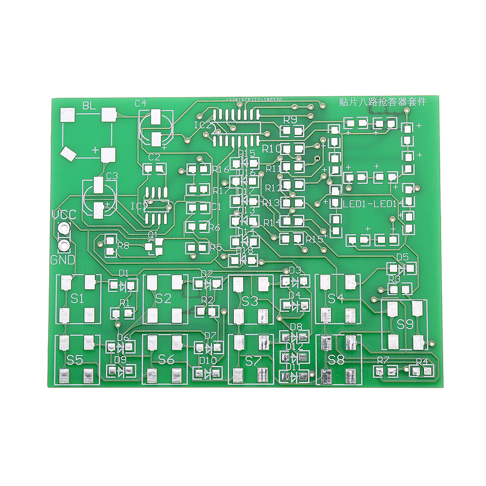
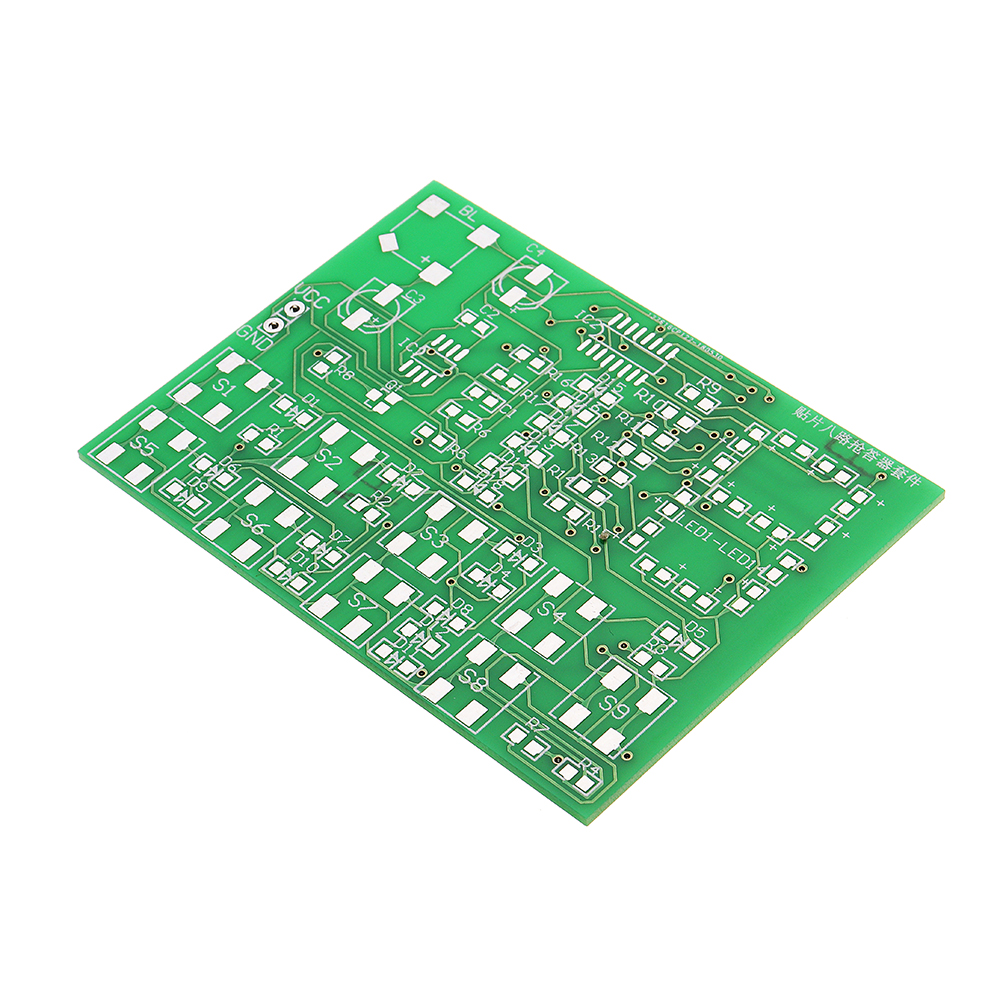
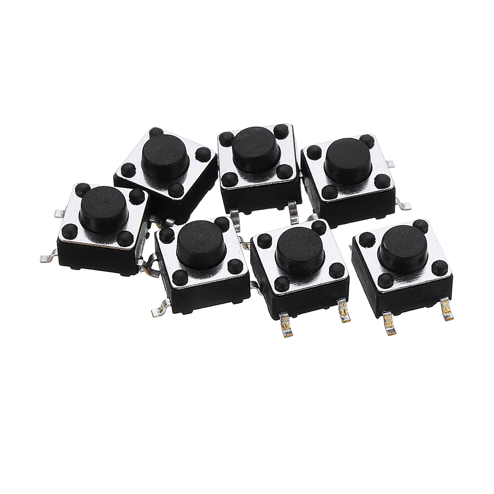
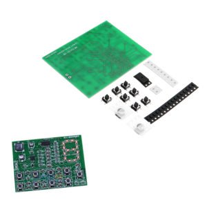
The circuit includes responder, coding, priority, latch, digital display and reset circuit. At the same time, the eight-way priority response can be carried out. When the button is pressed, the buzzer sounds. At the same time (light emitting diode) shows the number of the priority response. After the successful response, the display will not change unless the reset key is pressed. After reset, display cleared, can continue to answer. S1-S8 is the answer key, and S9 is the reset key. CD4511 is an integrated circuit with BCD-7 segment latch/decode/drive circuit. Among them, 1, 2, 6 and 7 are BCD code input terminals, 9-15 pins are display output terminals, 3 pins (LT) are test output terminals. When “LT” is 0, all outputs are 1,4 pins (BI) as blanking terminals, and when BI is 0, all outputs are 0 and 5 pins (LE) are latch permissible. At the end, when the LE is changed from “0” to “1”, the output terminal keeps the display state of LE at 0. 16 feet for power supply, 8 feet for power supply negative. 555 and peripheral circuits constitute the Responder circuit. Digital display is composed of light emitting diodes (pay attention to polarity when welding, one end of two white lines on PCB board is negative pole).
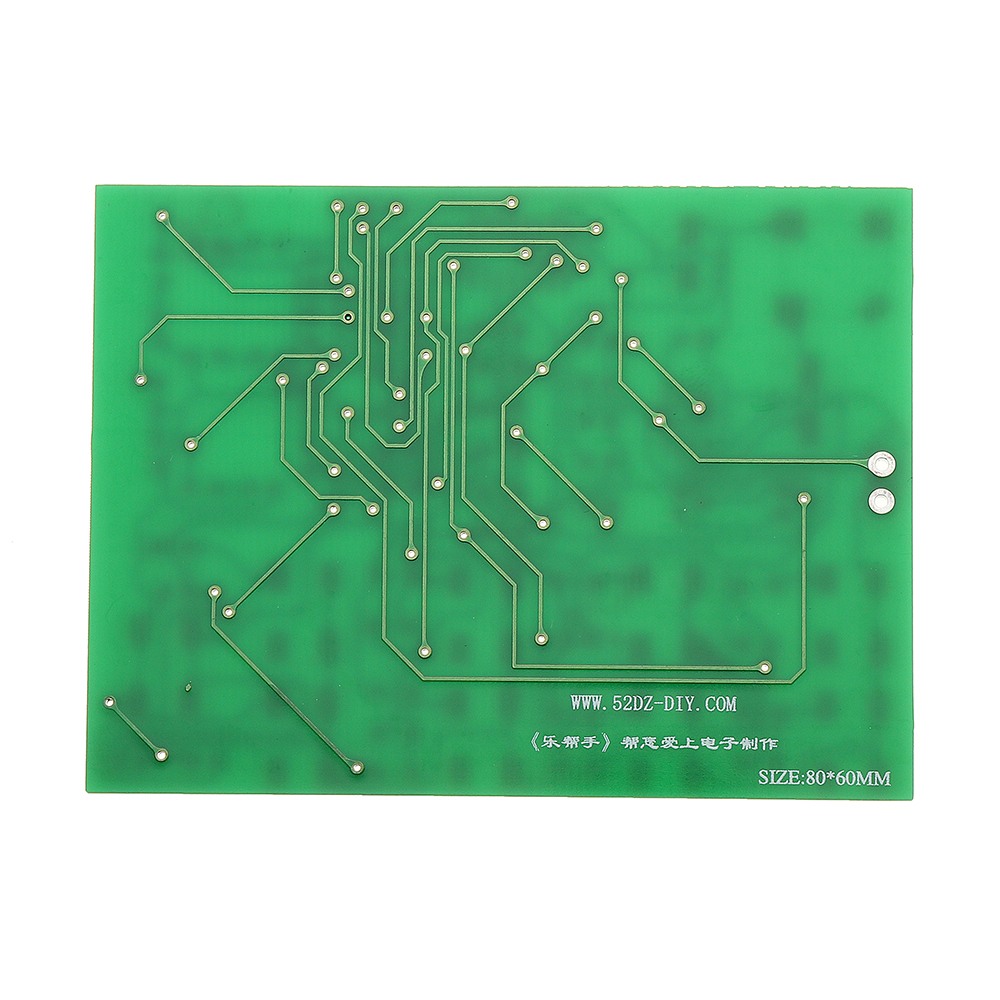
Size: 80 x 60mm
Material: double side 1.6mm FR-4 sheet
Size: 80 x 60mm
Material: double side 1.6mm FR-4 sheet
Package Included:
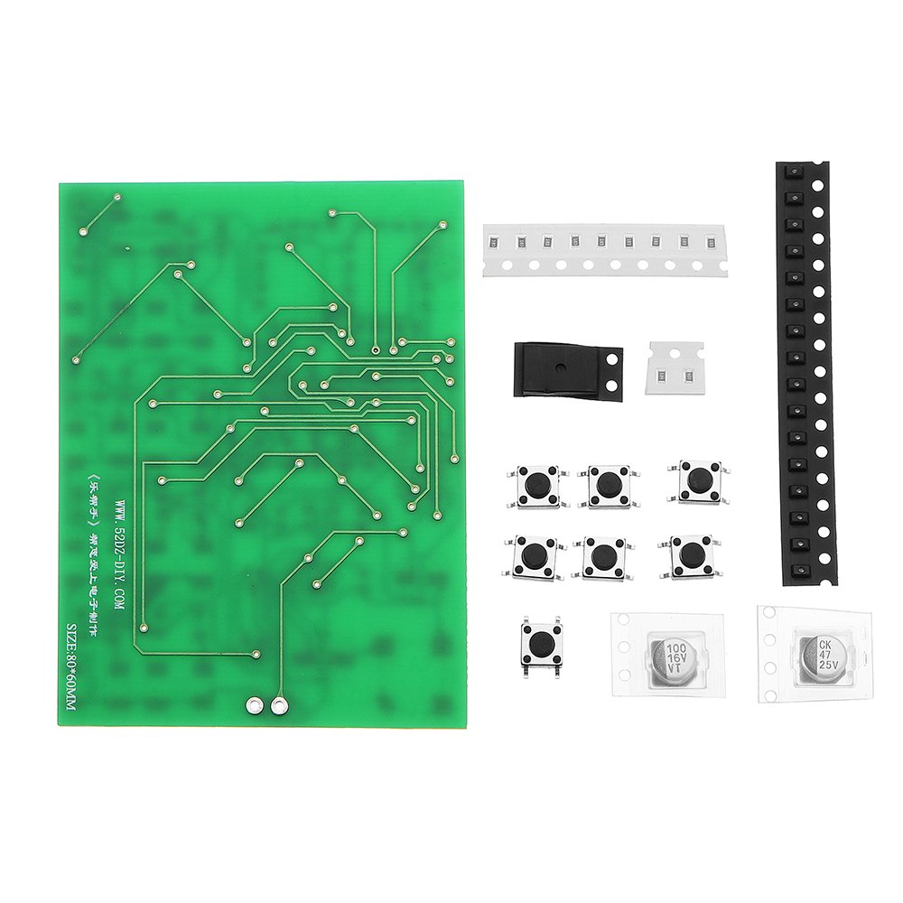
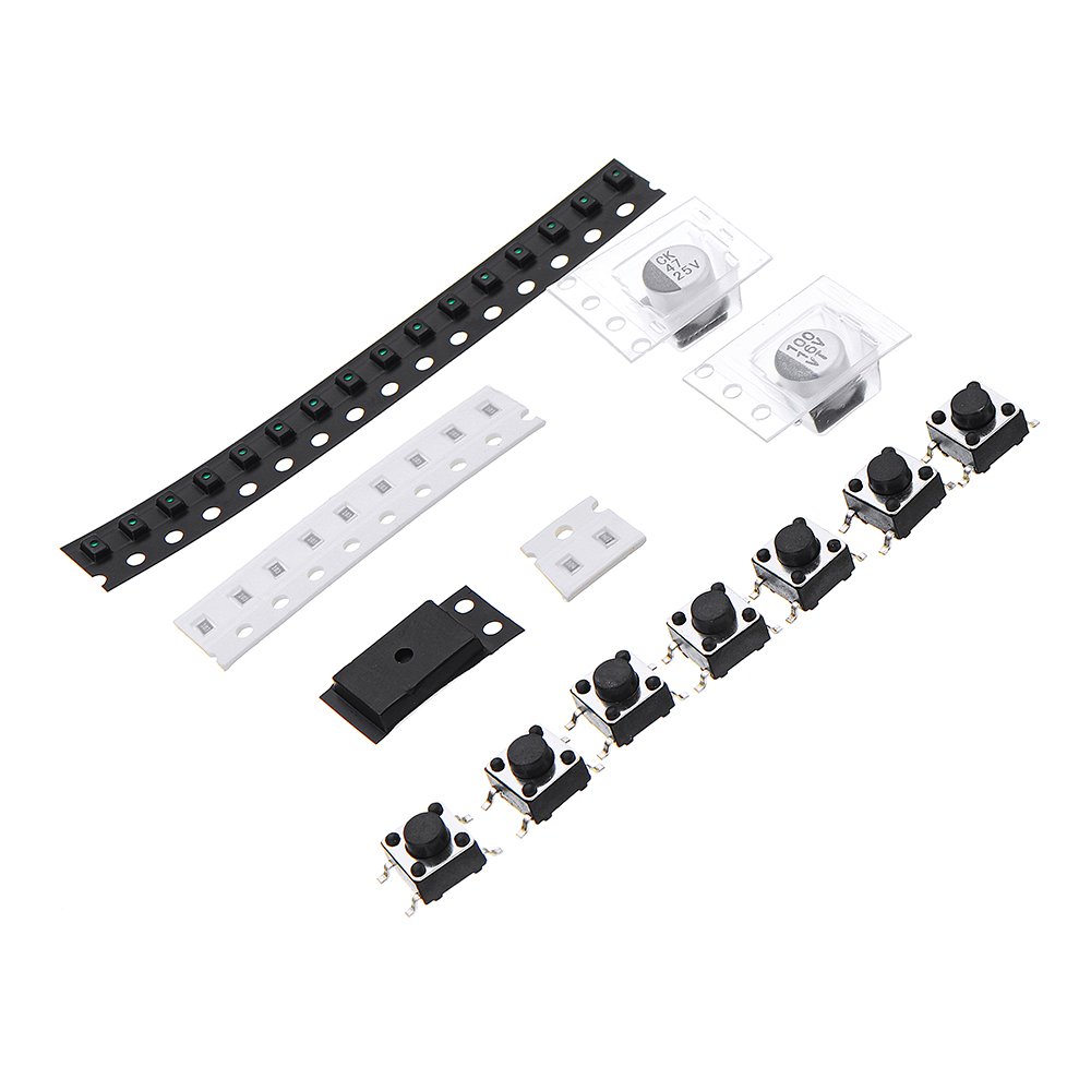
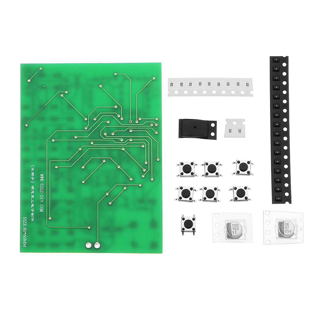
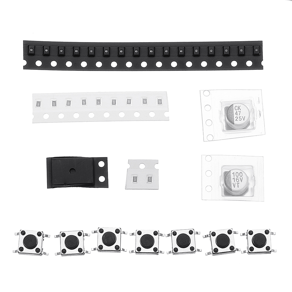
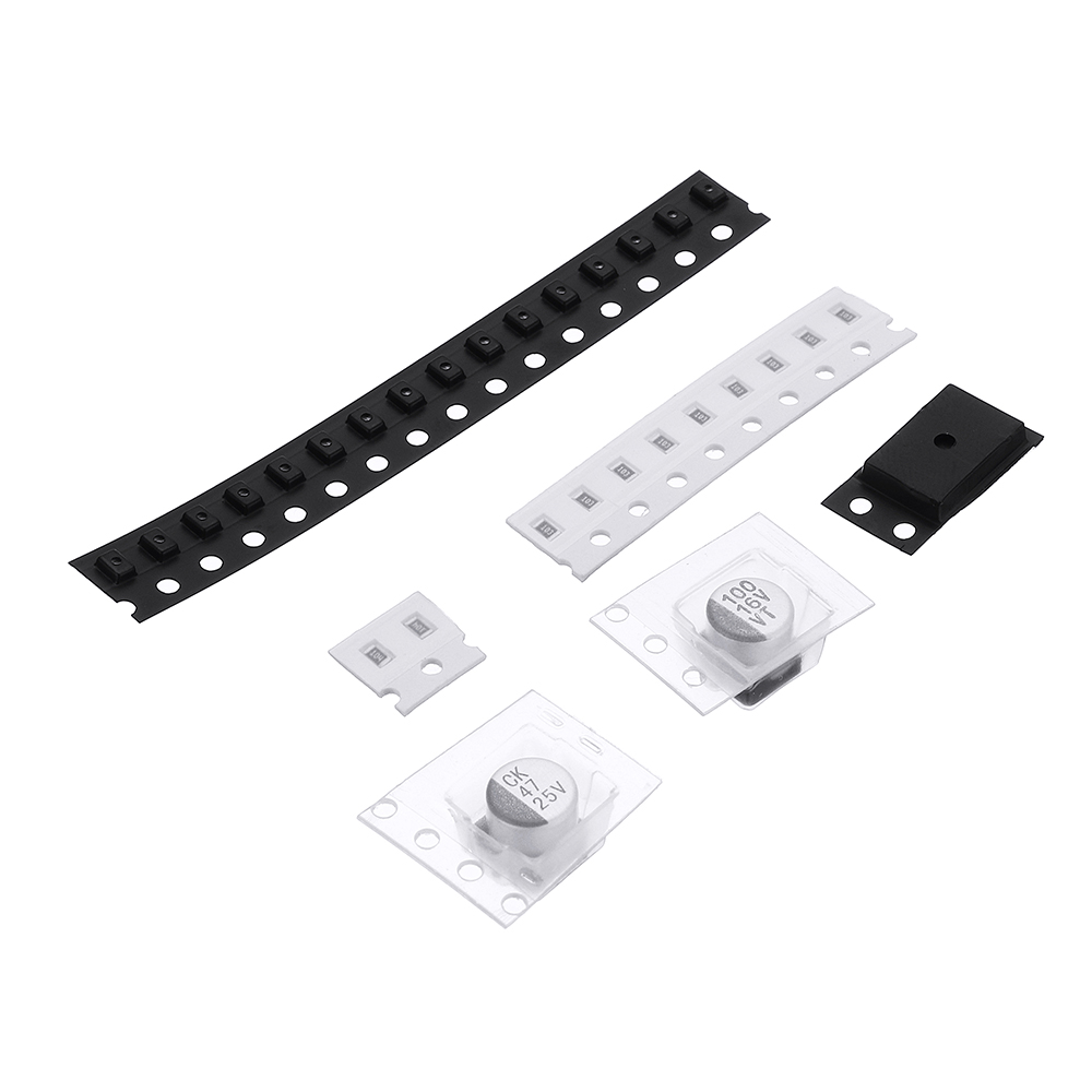
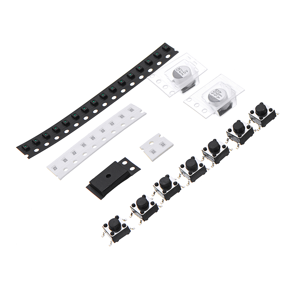
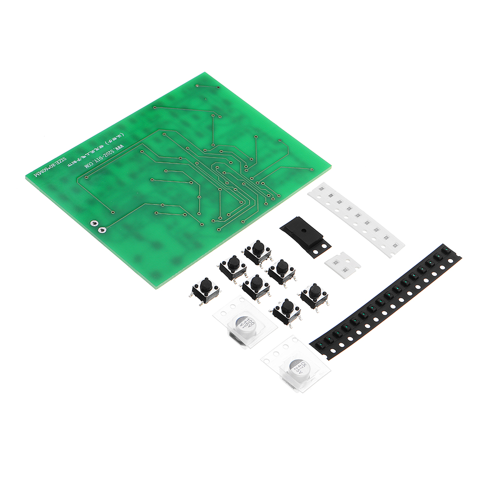
1 x DIY All Paster 8 Channel Digital Responder Kit





 or 4 payments of

Reviews
There are no reviews yet.